



Silicon carbide (SiC) has been one of the main components of abrasive technology for decades now. Exceptional hardness (9.5 on the Mohs scale), thermal conductivity and abrasive nature of SiC make it a key component in dealing with hard and brittle nonmetallic materials. Nonetheless, the real value of a silicon carbide grain is revealed only if the appropriate grit size is chosen. This single parameter decides on removal rate, surface quality and the general economy of the process. Choosing wrong grit size will cost you in terms of scrap, slow processing, and quick consumption of media. This article presents an overview of the technical aspects of choosing a correct grit size.
The Fundamental Principle: Geometry of the Material Removal
Choosing a correct grit starts with understanding the principles of the grit action. Each silicon carbide grain acts as a cutting tool with a specific geometric shape consisting of sharp points. The grit size parameter determines two main variables in this equation:
1. Depth of Cut (Chip Thickness): Larger grit extends further away from the bond or carrier matrix (depending on whether the abrasives are bonded or in suspension form such as slurries or blasting), hence allowing for a greater depth of cut. Larger chips are formed, which require more energy expenditure but remove larger volumes of material at each cutting point.
2. Mechanical Load per Cutting Point: In a situation where the load remains constant, coarse grits distribute the load at a smaller number of points and in doing so create very large mechanical loads. This leads to a fracture of even the hardest materials. Fine grits distribute the same load at a large number of microcutting points, which in turn produce insufficient mechanical pressure to cause a fracture; hence causing plastic deformation (plowing and rubbing).
Interpretation of Grit Size Specifications
The terminology for grit size specifications is standardized but needs explanation. The three major classifications are FEPA (Federation of European Producers of Abrasives), ANSI (American National Standards Institute), and JIS (Japanese Industrial Standard).
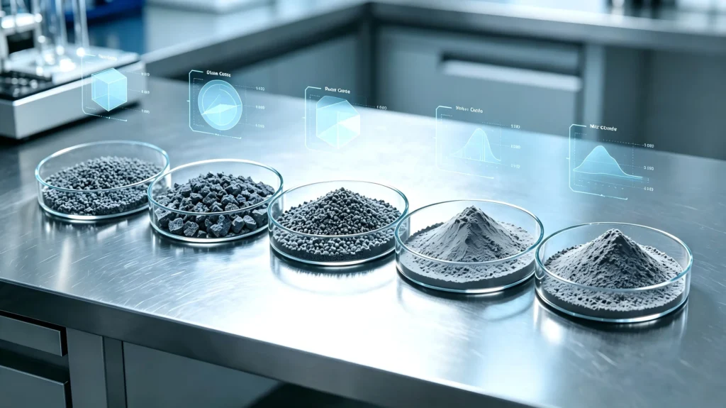
Macrogrits (FEPA F, ANSI): Based on mesh number, which indicates the number of openings per inch in the sieve screen. F60 means that the particles will pass through a sieve having 60 openings per inch. Lower Fnumber (such as F16) means fewer openings and larger particle sizes, whereas higher Fnumber (such as F120) means greater openings and smaller particles.
Microgrits (FEPA P, JIS): Indicated by the physical size of the particle in micrometers (µm). An F800 microgrit has a median particle size of 6.5 µm. In this case, the larger the number, the finer is the grit.
Not only is the size of a given particle significant but also the PSD. The more precise the PSD control, the better the results. In a wide PSD, even a coarse F24 grit will have some particles that will polish and several others that will scratch deep and unexpectedly. As for precision applications, one should pay as much attention to the PSD specification as to the nominal size.
Abrasive Sieve Size and Mesh Opening Comparison Table
| Sieve Size | Aperture (mm) | Wire Diameter (mm) | Open Area(%) |
| 5# | 4 | 1 | 64 |
| 5.5# | 3.55 | 0.9 | 63 |
| 6# | 3.35 | 0.8 | 65 |
| 6.5# | 3.15 | 0.8 | 63 |
| 7# | 2.8 | 0.71 | 63 |
| 7.5# | 2.5 | 0.63 | 64 |
| 8# | 2.36 | 0.56 | 65 |
| 9# | 2.24 | 0.56 | 64 |
| 10# | 2 | 0.5 | 64 |
| 10.5# | 1.9 | 0.5 | 63 |
| 11# | 1.8 | 0.45 | 64 |
| 12# | 1.7 | 0.45 | 63 |
| 12.5# | 1.6 | 0.45 | 61 |
| 13# | 1.5 | 0.4 | 62 |
| 14# | 1.4 | 0.4 | 60 |
| 14.5# | 1.32 | 0.4 | 59 |
| 15# | 1.25 | 0.4 | 57 |
| 16# | 1.18 | 0.4 | 56 |
| 16.5# | 1.12 | 0.355 | 58 |
| 17# | 1.06 | 0.355 | 56 |
| 18# | 1 | 0.355 | 54 |
| 18.5# | 0.95 | 0.315 | 55 |
| 19# | 0.9 | 0.315 | 54 |
| 20# | 0.85 | 0.315 | 53 |
| 22# | 0.8 | 0.28 | 52 |
| 24# | 0.75 | 0.28 | 53 |
| 25# | 0.71 | 0.28 | 51 |
| 27# | 0.67 | 0.28 | 50 |
| 29# | 0.63 | 0.25 | 51 |
| 30# | 0.6 | 0.25 | 50 |
| 32# | 0.56 | 0.224 | 51 |
| 34# | 0.53 | 0.224 | 49 |
| 35# | 0.5 | 0.224 | 48 |
| 38# | 0.475 | 0.18 | 53 |
| 39# | 0.45 | 0.18 | 51 |
| 40# | 0.425 | 0.16 | 53 |
| 42# | 0.4 | 0.16 | 51 |
| 44# | 0.375 | 0.16 | 49 |
| 45# | 0.355 | 0.14 | 51 |
| 47# | 0.335 | 0.14 | 50 |
| 48# | 0.315 | 0.14 | 48 |
| 50# | 0.3 | 0.14 | 46 |
| 54# | 0.28 | 0.14 | 44 |
| Sieve Size | Aperture (mm) | Wire Diameter (mm) | Open Area(%) |
| 57# | 0.265 | 0.125 | 43 |
| 60# | 0.25 | 0.125 | 44 |
| 65# | 0.236 | 0.125 | 43 |
| 68# | 0.224 | 0.125 | 41 |
| 70# | 0.212 | 0.215 | 40 |
| 75# | 0.2 | 0.125 | 38 |
| 78# | 0.19 | 0.125 | 36 |
| 80# | 0.18 | 0.125 | 35 |
| 85# | 0.17 | 0.1 | 36 |
| 90# | 0.16 | 0.1 | 35 |
| 100# | 0.15 | 0.1 | 36 |
| 110# | 0.14 | 0.09 | 37 |
| 115# | 0.132 | 0.09 | 35 |
| 120# | 0.125 | 0.09 | 34 |
| 125# | 0.118 | 0.063 | 42 |
| 130# | 0.112 | 0.063 | 41 |
| 140# | 0.106 | 0.063 | 39 |
| 150# | 0.1 | 0.063 | 38 |
| 160# | 0.095 | 0.063 | 36 |
| 170# | 0.09 | 0.063 | 35 |
| 180# | 0.085 | 0.056 | 36 |
| 190# | 0.08 | 0.056 | 35 |
| 200# | 0.075 | 0.05 | 34 |
| 210# | 0.071 | 0.056 | 31 |
| 220# | 0.067 | 0.05 | 34 |
| 230# | 0.063 | 0.045 | 34 |
| 240# | 0.06 | 0.045 | 33 |
| 260# | 0.056 | 0.045 | 33 |
| 270# | 0.053 | 0.04 | 33 |
| 290# | 0.05 | 0.036 | 34 |
| 300# | 0.048 | 0.036 | 35 |
| 325# | 0.045 | 0.036 | 31 |
| 340# | 0.042 | 0.036 | 31 |
| 360# | 0.04 | 0.03 | 31 |
| 400# | 0.038 | 0.0332 | 29 |
| 420# | 0.036 | 0.03 | 30 |
| 450# | 0.032 | 0.025 | 31 |
| 500# | 0.028 | 0.025 | 28 |
| 520# | 0.025 | 0.025 | 26 |
| 550# | 0.022 | 0.02 | 25 |
| 600# | 0.02 | 0.02 | 24 |
| 800# | 0.015 | 0.018 | 23 |
| 1000# | 0.01 | 0.015 | 20 |
The Core Selection Matrix: Process-Specific Logic
Fundamental guidelines have to be adjusted to the physics of the industrial process. The same F120 grit will perform completely differently if used in a bonded form (grinding wheel or segments) or in a free form (slurry).
1. Bonded Abrasives (Grinding Wheels, Segments)
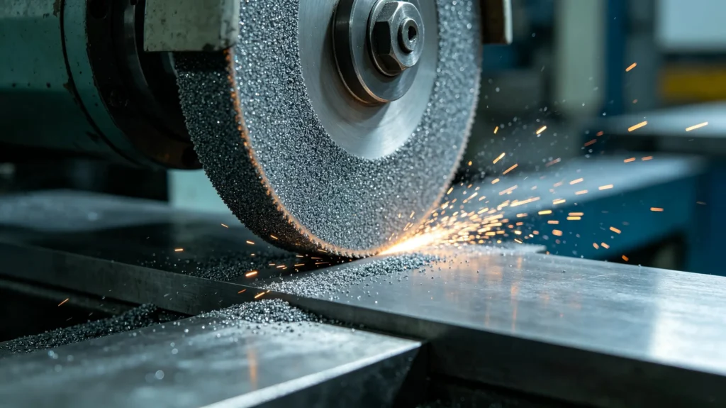
In this case, the grit is fixed in a bond system. The selection process is a dialectic of stock removal, surface finish, and thermal damage.
Coarse Grits (F16-F36): Foundry and steel mill workhorses. For high-pressure snagging operations, conditioning heavy billets, and material removal where surface finish is not important. The large chip clearance capacity avoids loading and produces less heat in the work piece, which is essential when working with heat-sensitive materials. Example: Cleaning titanium or super alloy castings where HAZ depth must be very shallow.
Medium Grits (F46-F80): General purpose range for surface, cylindrical and centerless grinding. A classic example would be an F60 ceramic bond silicon carbide wheel used for cemented carbides, cast irons, and non-ferrous metals (brass, aluminum). The grit is friable enough to auto sharpen, continually presenting sharp edges while being large enough to remove material. Example: Cast iron camshaft grinding, where cycle time and surface finish on bearing areas are balanced.
Fine Grits (F100–F220): This is the realm of finish grinding. This is used when Ra values become less than 0.4 µm. It is at this point that the process of microfracture takes place. A soft-bond F180 wheel on a bronze or stainless steel roll would produce almost a mirror finish, with the material being removed by means of microcutting and plastic flow. There is always the danger of glazing because the bond has to be soft to let go of the worn out abrasive particles before rubbing results in burning.
2. Lapping and Polishing (Abrasive Powder)
This is an entirely different process. The grit is a free roller hydrodynamically between a lapping disc and the work piece.
Stock Removal Lapping (F320-F600/29.2-9.3µm): Stock removal lapping involves controlled fracturing. Rolling silicon carbide particles create indentations on the surface, which leads to development of transverse and median cracks that intersect and produce material removal. The main purpose of this process is rapid planarization of the surface and removal of stock generated by the preceding process (e.g., fine grinding). A typical initial lapping solution for silicon wafers, ceramic seal faces, and optical glass substrates is an F400 slurry on cast iron plate. It produces matte, nonglossy surface with substantial SSD.
Precision Polishing (F800-F1200 / 6.5-3.0µm): Once the particle size drops below the critical depth of cut of the material, the process moves from the brittle fracture zone into the ductile one. Rather than causing deep cracks through the surface, the abrasive cuts a shallow groove and plastically displaces the material sideways. This technique reduces the SSD significantly while effectively removing the layer of damage left after lapping. F1000 silicon carbide in a tin or composite polishing pad is applied to polish the advanced ceramic substrate down to the damage-free and optically flat surface in preparation for further chemical-mechanical polishing (CMP). In this case, the PSD should be extremely narrow; even one rogue particle of 15 µm size in F1200 suspension may fatally scratch the surface for future laser optics usage.
3. Wire Sawing (Slurry-based)
The traditional process relies on entraining abrasives in a liquid medium that moves the wire. Traditionally, the model uses F800 or F1000 silicon carbide. It is worth noting that the wire itself does not cut anything, while the abrasive particles do the job. It is vital to ensure that the grit particles are large enough to form a kerf larger than the wire and slurry film to prevent the wire from catching up with itself but small enough to reduce kerf loss and subsurface damage to a minimum. The emergence of diamond wire sawing has made this type of slurry-grit system obsolete.
4. Abrasive Blasting
In this case, the selection is dictated by kinetic energy of the particle and the desired surface profile.
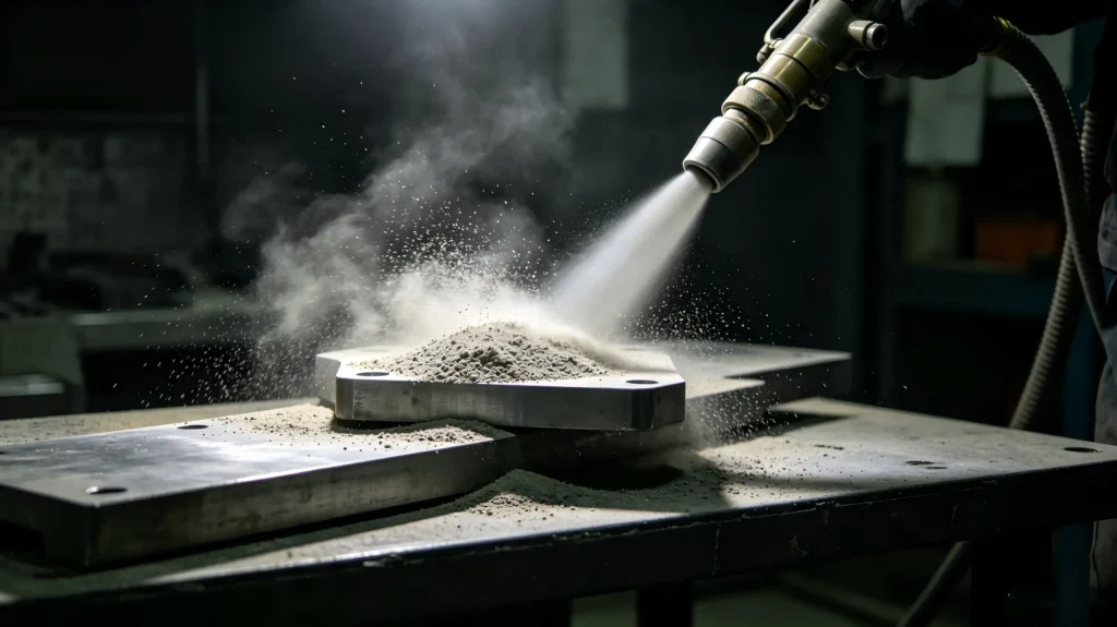
• Stripping and Profiling (F16-F36): High energy, large grit size. The objective here is not a finish but mechanical anchoring. Stripping the steel bridge girder using F20 silicon carbide results in an angular profile (75-125 µm), which is crucial for the anchorage of thermal spray coating or high build industrial painting. Angularity of the grit size is critical; otherwise, if round media were to be used, the surface would get peened rather than cut.
• Surface Cleaning and Cosmetic Finishing (F60-F120): This is used at low pressure for tasks such as deburring, satin finishing, and cleaning oxide scale without altering critical dimensions. F80 grit size at 40-60 PSI is ideal for preparing complex bronze art casting for patination, where the investment shell is stripped away to produce a uniformly matte-silver finish.
• Microblasting for Tooling (F320-F600): This involves precision edge honing of carbide cutting inserts using pinpoint nozzles. An F500 particle size can produce a very precise 20-30 µm radius on the edge of a tool without affecting its macrogeometry by eliminating micro-chips caused during grinding process.
The Critical Interplay: Grit Size, Material, and Subsurface Damage
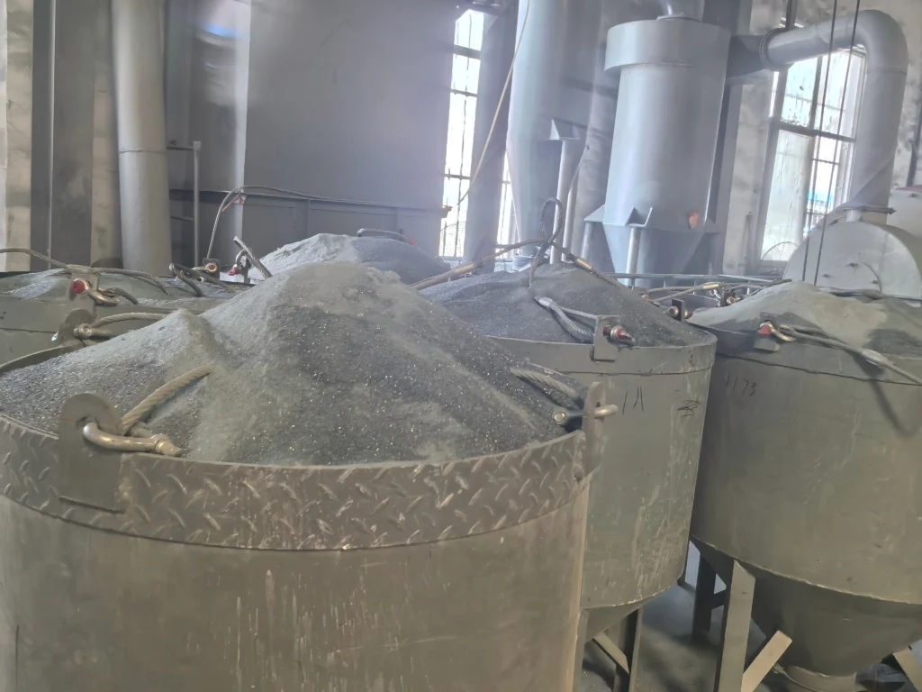
The most complicated choice is associated with SSD control, in ceramics, semiconductors, and optical materials. The SSD is a series of cracks formed below the surface of the finished product. The depth of such cracks is approximately proportional to the size of abrasive grains used at the penultimate stage of processing.
This results in a primary rule that the stock removal of each subsequent process should be larger than the subsurface damage depth of the previous process. A process engineer designs not a particular grit size but rather a series of grit sizes.
Typical grinding and polishing series for a sintered silicon carbide mechanical seal face could be like:
1. F60 Grind: Fast stock removal. SSD depth around 30-40 µm.
2. F220 Grind: Stock removal of 50 µm (SSD elimination from step 1). Produces 0.4 µm Ra surface with SSD about 6-8 µm.
3. F400 Lap: Removal of 15 µm of stock (SSD elimination from step 2). Produces matt surface with SSD about 2-3 µm.
4. F1200 Polish: Removal of 5 µm of stock (SSD elimination from step 3). Produces mirror surface with SSD less than 1 µm.
If you violate the sequence (for instance, try to perform polishing right after F60 grind) it will be a useless job since all you will manage to do is to round off the peaks of the deep crack topography but never remove the cracks.
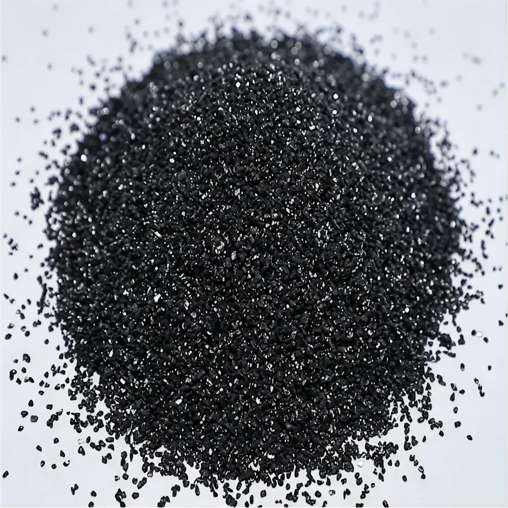
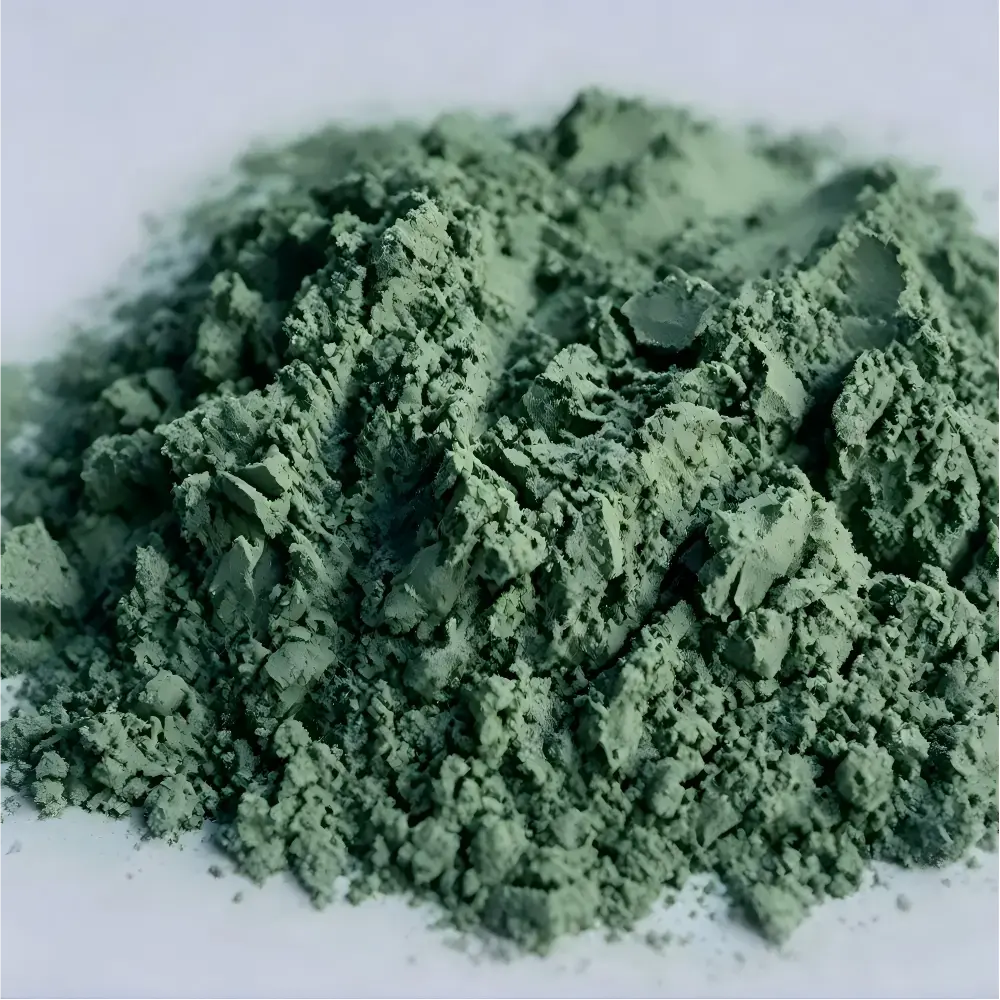
Two Cases of Interest in Silicon Carbide Uses
Case 1: Grinding of Non-Ferrous Materials (aluminum and brass)
Although silicon carbide is the better choice of the two grinding stones compared to aluminum oxide because the latter has a high chemical affinity, and gets loaded quickly, the nature of the ductile material requires careful selection of grit sizes.
The coarse, open structure of the wheel (F24F36) is imperative during roughing to avoid the “gumming up” effect due to the formation of sticky and long chips.
When doing finishing operations, F80F100 wheels must be used with friable and soft bonding to ensure the microfracture of the grains, producing sharp cutting edges to shear the metal. The use of a fine but hard acting bond is the most common mistake when doing this task.
Case 2: Machining Advanced Ceramics (Alumina, Zirconia, Silicon Carbide itself)
Hardness of this material and its complete lack of ductility dictate that machining can only take place through brittle fracture, and then transition to ductile grinding regime.
Roughing: Apply F80F100 grit with resin bond. This is paradoxically “fine” grit as compared to metal machining. If coarser grit like F36 is used to grind dense finegrained ceramic, then the point pressure will be so high that it results in uncontrolled conchoidal fracture of material at edge and into the bulk, leading to catastrophic weakening of part.
Finishing: This process is completely dictated by ductile transition process. Critical depth of cut for silicon carbide ceramic may be as low as 0.1-0.2 µm. It requires grinding wheel with F1200 or finer grit, and on an ultrarigid precision machine. “Grit” is not so much individual abrasive particle but rather field of points producing hydrostatic stress field enabling plastic flow.
Conclusion: A Systematic Approach to Selecting the Right Size Grit
The selection of the right size of silicon carbide grit for your process is not an art but an engineering procedure. To reduce risk, follow this structured approach:
1. Determine the requirements of the end-product: Surface finish (Ra in µm or Å), subsurface damage (SSD), and flatness/figure requirements.
2. Determine the amount of stock to be removed: From the raw material condition to the final product.
3. Design your grit sequence backward: Start from the last polishing step and select the right grit size which will give you the required finish and SSD. Then go back to the previous polishing step and choose the grit whose SSD can be economically removed by the last step. Go on with this backward design till the requirement of stock removal is fulfilled.
4. Specify the process-specific parameters of the selected grit. In order to ensure that the grit works in its appropriate removal mode (either brittle fracture or ductile flow), choose the appropriate bond and grade (for grinding operations), the carrier and plate (for lapping operations), or the pressure and nozzle shape (for blasting operations).
5. Control the Particle Size Distribution strictly: The nominal grit size is worthless without the control of its distribution. A highquality F600 grit with narrow particle size distribution will perform much better than cheap F600 grit which consists mainly of fines and large aggregates, especially in brittle materials.
Due to its extreme sharpness and hardness silicon carbide is both an instrument of precise surgery and destructive brutality – depending on the grit size of course.

Contact Our SiC Technical Team➡️
·Struggle to select proper silicon carbide grit size for your production?
·Our engineers customize matched SiC grains & micropowder per FEPA / JIS standards.
·Free sample testing & full particle size distribution reports available.
Looking for High-Purity Silicon Carbide Grains or Powder?
Contact our technical team for custom grit sizes and wholesale quotes.
Get a Free Quote

